Building A
Weather Station
In this project we combine the Arduino micro-controller with sensors to detect barometric pressure, temperature, and relative humidity.
This is the completed project.
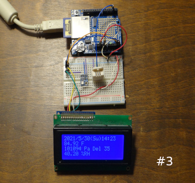
Components are pictured below.
One of the nice features of the Arduino design is its ability to accomadate plug-in boards, called shields. The shield in use above is a data logger. It has the ability to store data on an SD card, and has a built in real time clock with a battery backup.
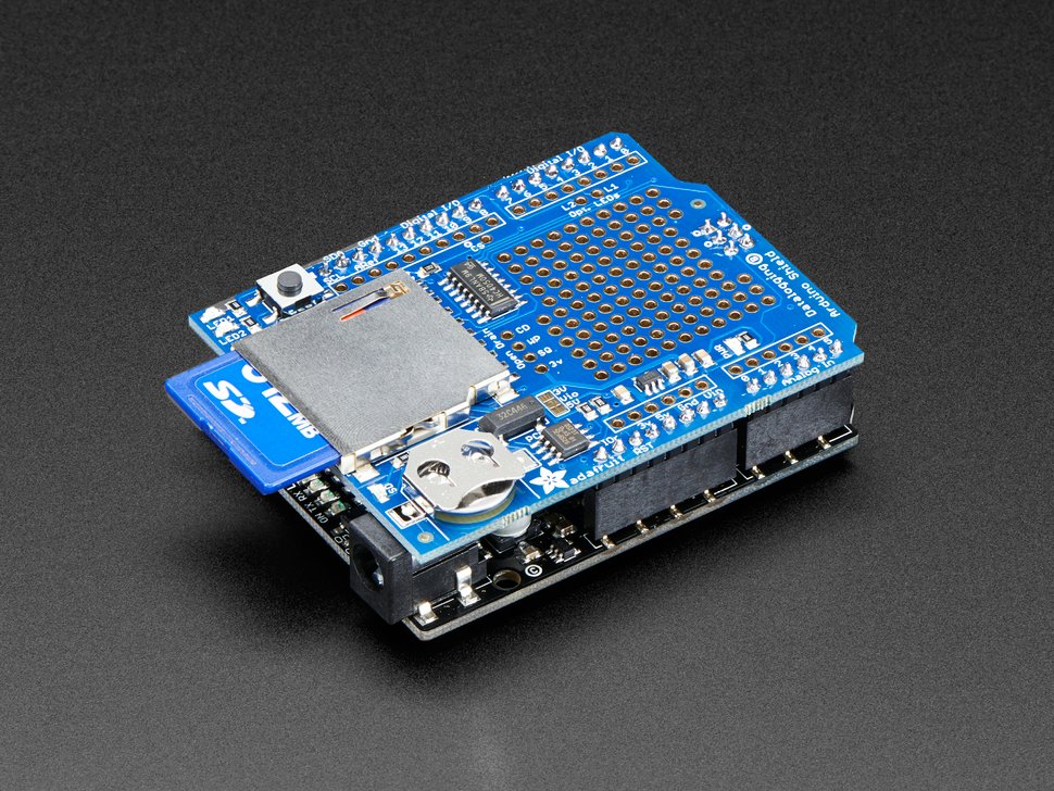
The Arduino fitted with a data shield
The BMP 180 pressure sensor is quite small. The breakout board measures 3/8 of an inch. The sensor, the small metal box on the board is around 1/8 in on a side. Wile the sensor is designed for 3.3 Volts, chips on the board allow it to be safely connected to a 5 volts source. This sensor reads the pressure in Pascals and then transmits the number of Pascals over a serial line using I2C technology.
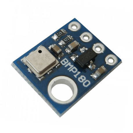
The BMP 180 pressure sensor
The humidity sensor measures 1/2 by 5/8 inches. This sensor reads the %RH and transmits that value serially using SPI technology.
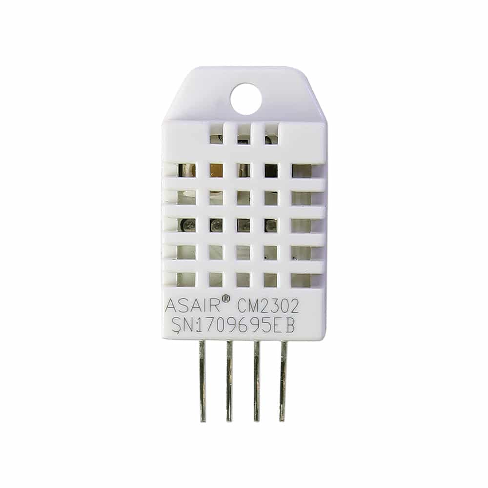
The ASAIR humidity sensor.
The backpack, circled in the image, plugs into the rear of the LCD display. It reduces the number of connections need from 12 to only 4.
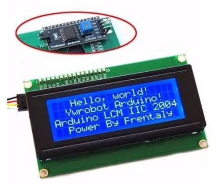
The four line LCD plus I2C backpack.
The wiring Diagram
A wiring diagram follows, but for those who might want to recreate this project the following table of connections might be more helpful.| Arduino Pins | 5 | 4 | 3 | Gnd | 5V |
| Arduino Function | SCL | SDA | Data | Gnd | 5V |
| BMP 180 | SCL | SDA | NC | Gnd | 5V |
| LCD I2C Backpack | SCL | SDA | NC | Gnd | 5V |
| Humidity Sensor | NC | NC | Data | Gnd | 5V |
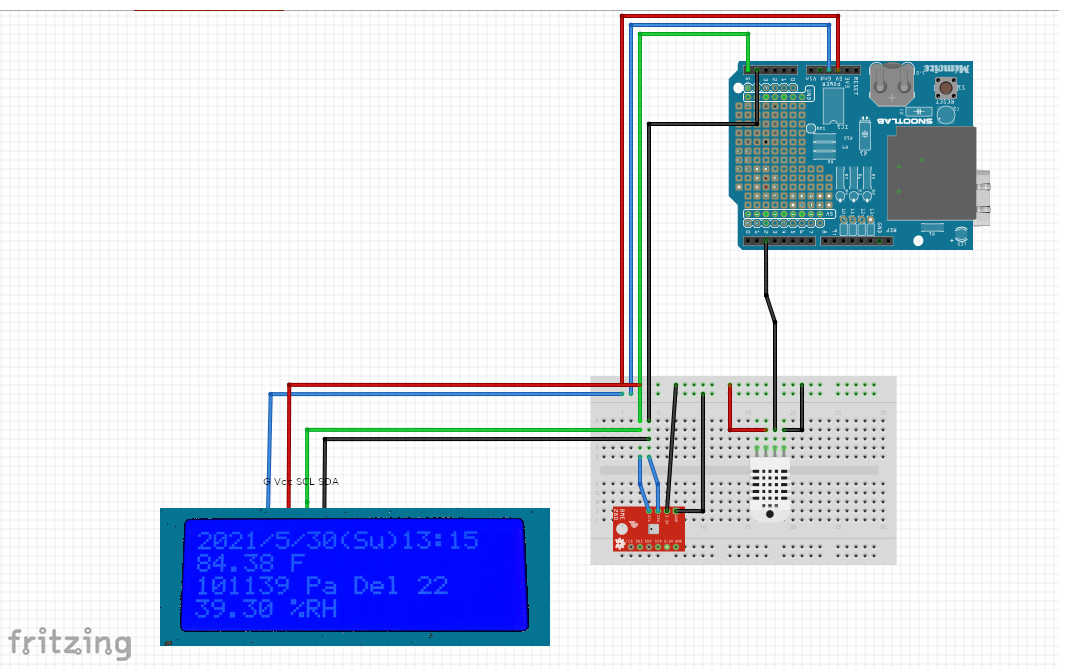
Some parts on the wiring diagram look different from the ones I used in my project. Sensors usually come on breakout boards, and breakout boards vary in layout. Also, not every device is available for use with the Fritzing software used to create the wiring diagram. As long as you make the connections outlined in the above table to the appropriate pins on your device you should be fine.
Initial Results
The following is a sample output from the SD card.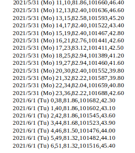
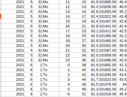
Here is what the comma / and () separated data looks
like when ported to a spreadsheet.
The following is an example of plotting barometric
pressure over a relatively short time.
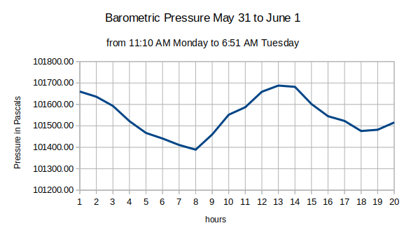
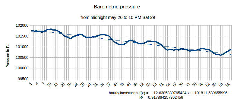
Barometric pressure changes slowly with time. The
following shows a trend over a much longer time interval.
The Code
//****************Libraries and variables********************

#include "RTClib.h"
RTC_PCF8523 rtc;

char daysOfTheWeek[7][12] = {"Su", "Mo", "Tu", "Wed", "Th", "Fr",
"Sa"};

#include  //load sd library
#include //load SPI comminication library
int chipSelect = 10; //set chipSelect.
File mySensorData; //variable for working with our file object

#include
Adafruit_LiquidCrystal lcd(0);
#include "DHT.h"
#define DHTPIN 2 //the pin we are connected to
#define DHTTYPE DHT22 //(AM2302)
#include "Wire.h"
#include "Adafruit_BMP085.h"

Adafruit_BMP085 bmp;//create an instance

DHT dht(DHTPIN, DHTTYPE); //create an instance

long b1=0;//variable to hold first reading
long b2=0;
long b3;//variable to hold the second reading
long delta=0;//variable to hold the change.
int i=0;
void setup() {
Serial.begin(9600);
dht.begin(); //begin is a function in dht
bmp.begin();
lcd.begin(16, 4);
SD.begin(chipSelect); //initialize the SD card with chipselect
connected to pin 4

//***********************clock***********************
#ifndef ESP8266
while (!Serial); // wait for serial port to connect. Needed for
native USB
#endif

if (! rtc.begin()) {
Serial.println("Couldn't find RTC");
Serial.flush();
abort();
}

if (! rtc.initialized() || rtc.lostPower()) {
Serial.println("RTC is NOT initialized, let's set the time!");
// When time needs to be set on a new device, or after a power
loss, the
// following line sets the RTC to the date & time this sketch was
compiled
rtc.adjust(DateTime(F(__DATE__), F(__TIME__)));
// This line sets the RTC with an explicit date & time, for
example to set
// January 21, 2014 at 3am you would call:
// rtc.adjust(DateTime(2014, 1, 21, 3, 0, 0));
//
// Note: allow 2 seconds after inserting battery or applying
external power
// without battery before calling adjust(). This gives the
PCF8523's
// crystal oscillator time to stabilize. If you call adjust()
very quickly
// after the RTC is powered, lostPower() may still return true.
}

// When time needs to be re-set on a previously configured
device, the
// following line sets the RTC to the date & time this sketch was
compiled
// rtc.adjust(DateTime(F(__DATE__), F(__TIME__)));
// This line sets the RTC with an explicit date & time, for
example to set
// January 21, 2014 at 3am you would call:
// rtc.adjust(DateTime(2014, 1, 21, 3, 0, 0));

// When the RTC was stopped and stays connected to the battery,
it has
// to be restarted by clearing the STOP bit. Let's do this to
ensure
// the RTC is running.
rtc.start();

// The PCF8523 can be calibrated for:
//        - Aging adjustment
//        - Temperature compensation
//        - Accuracy tuning
// The offset mode to use, once every two hours or once every
minute.
// The offset Offset value from -64 to +63. See the Application
Note for calculation of offset values.
// https://www.nxp.com/docs/en/application-note/AN11247.pdf
// The deviation in parts per million can be calculated over a
period of observation. Both the drift (which can be negative)
// and the observation period must be in seconds. For accuracy
the variation should be observed over about 1 week.
// Note: any previous calibration should canceled prior to any
new observation period.
// Example - RTC gaining 43 seconds in 1 week
float drift = 43; // seconds plus or minus over observation
period - set to 0 to cancel previous calibration.
float period_sec = (7 * 86400);  // total observation period
in seconds (86400 = seconds in 1 day:  7 days = (7 * 86400)
seconds )
float deviation_ppm = (drift / period_sec * 1000000); //
deviation in parts per million (μs)
float drift_unit = 4.34; // use with offset mode PCF8523_TwoHours
// float drift_unit = 4.069; //For corrections every min the
drift_unit is 4.069 ppm (use with offset mode PCF8523_OneMinute)
int offset = round(deviation_ppm / drift_unit);
// rtc.calibrate(PCF8523_TwoHours, offset); // Un-comment to
perform calibration once drift (seconds) and observation period
(seconds) are correct
// rtc.calibrate(PCF8523_TwoHours, 0); // Un-comment to cancel
previous calibration

Serial.print("Offset is ");
Serial.println(offset); // Print to control offset
//*****************************clock****************************
}

void loop() {

float h = dht.readHumidity();
float t = dht.readTemperature(); //Celsius

delay(10000);
lcd.clear();

if (isnan(h) || isnan(t)) {
Serial.println("Failed to read from FHT sensor!");
return;
}
if (!bmp.begin()) {
Serial.println("Could not find a valid BMP085 sensor, check
wiring!");
while (1) {}
}


Serial.print("Pressure= ");
Serial.print(bmp.readPressure());

Serial.print( " Pa");
//Serial.print(" Start ");
Serial.print(" ");
Serial.print(b1);
Serial.print(" ");
Serial.print(b3);
Serial.print(" D ");
Serial.println(delta);

Serial.print("Baro Temp= ");
Serial.print(bmp.readTemperature() * 9 / 5 + 32);
Serial.println(" F ");

Serial.print("Humidity: ");
Serial.print(h);
Serial.println("%\t");

Serial.println();

//*******************Print to monitor************************
DateTime now = rtc.now();

Serial.print(now.year(), DEC);
Serial.print('/');
Serial.print(now.month(), DEC);
Serial.print('/');
Serial.print(now.day(), DEC);
Serial.print(" (");
Serial.print(daysOfTheWeek[now.dayOfTheWeek()]);
Serial.print(") ");
Serial.print(now.hour(), DEC);
Serial.print(':');
Serial.print(now.minute(), DEC);
Serial.print(':');
Serial.print(now.second(), DEC);
Serial.println();


//************************Write to the LCD display*************
lcd.setCursor(0, 0);
lcd.print(now.year(), DEC);
lcd.print('/');
lcd.print(now.month(), DEC);
lcd.print('/');
lcd.print(now.day(), DEC);
lcd.print("(");
lcd.print(daysOfTheWeek[now.dayOfTheWeek()]);
lcd.print(")");
lcd.print(now.hour(), DEC);
lcd.print(':');
lcd.print(now.minute(), DEC);

lcd.setCursor(0, 1);
lcd.print(bmp.readTemperature() * 9 / 5 + 32);
lcd.print(" F");

lcd.setCursor(0, 2);
lcd.print(bmp.readPressure());
lcd.print(" Pa");
lcd.print(" Del ");
lcd.print(delta);

lcd.setCursor(0, 3);
lcd.print(h);
lcd.print(" %RH");

//this code is used to check the change in barometric pressure
for a given time interval

Serial.print(now.year(), DEC);
Serial.print('/');
Serial.print(now.month(), DEC);
Serial.print('/');
Serial.print(now.day(), DEC);
Serial.print(" (");
Serial.print(daysOfTheWeek[now.dayOfTheWeek()]);
Serial.print(") ");
Serial.print(now.hour(), DEC);
Serial.print(':');
Serial.print(now.minute(), DEC);
Serial.print(':');
Serial.print(now.second(), DEC);
Serial.println();
i=i+1;
Serial.println(i);
//readings are refreshed every 10 seconds.
//this will happen 360 times in one hour.
//when the count is greater than 359, or 360, the second reading
is compared to the one
//taken at the beginning of the time interval. Change the value
of the test count-1 to
//use a different time interval.
if(i>359){  //creates a time between readings of one hour.
Serial.println("now writing to disk");

//********************Write to the SD card*******************
mySensorData = SD.open("PTData.txt", FILE_WRITE); //open
FTData.txt on the SD card as a file to write to
if (mySensorData) { //if file opens

DateTime now = rtc.now();

mySensorData.print(now.year(), DEC);
mySensorData.print('/');
mySensorData.print(now.month(), DEC);
mySensorData.print('/');
mySensorData.print(now.day(), DEC);
mySensorData.print(" (");
mySensorData.print(daysOfTheWeek[now.dayOfTheWeek()]);
mySensorData.print(") ");
mySensorData.print(now.hour(), DEC);
mySensorData.print(',');
mySensorData.print(now.minute(), DEC);
mySensorData.print(",");
mySensorData.print(bmp.readTemperature() * 9 / 5 + 32); //write
temperature to SD card.
mySensorData.print(",");
mySensorData.print(bmp.readPressure());//write pressure
mySensorData.print(",");
mySensorData.println(h);//write humidity
mySensorData.close(); //close the file

}
i=0;
b2=bmp.readPressure();
delta=b1-b2;//display change relative to one hour prior

b1=b2;

}

}

