

- Home Page
- Arduino Main
- Arduino Projects
- Digital yardstick
- The speed of sound
- Barometer and %RH
- IR remote control-LED
- IR remote DC motor
- Relevant Links
- Paul McWhorter
How To Control A Motor
Using IR Remote
In this project an IR remote controller was combined with an Arduino and an H-bridge chip to control both the speed and direction of a small DC motor. The design includes 5 LEDs to indicate speed level, and two LED’s to indicate motor direction.
Summary
The decoded signals from two buttons on the remote were programmed to turn the motor clockwise or counterclockwise. Two additional buttons were programmed to control motor speed, one for incrementally faster, and the other slower. A fifth button was programmed to turn the motor off. Attached to the motor shaft is a one and a quarter inch diameter disk with a timing mark. This was used to determine motor speed. The following image shows the complete setup.
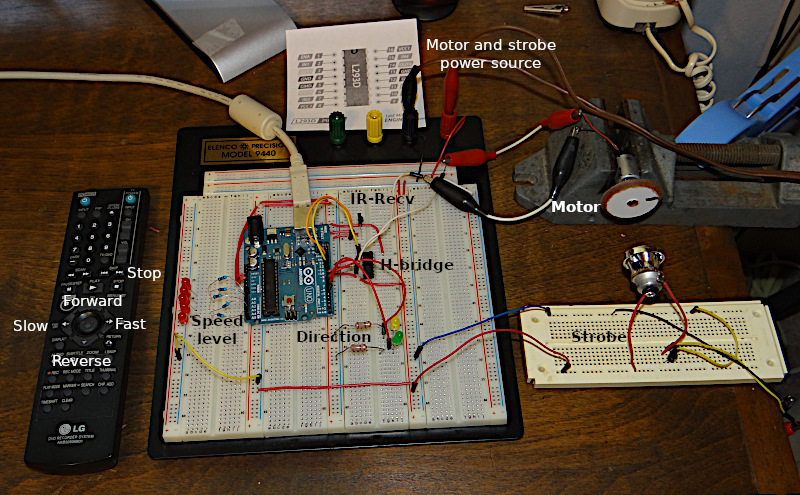
The smaller breadboard in front of the motor holds the stroboscope circuit. It consists of the head salvaged from an LED flashlight, a 2N2222 transistor, and a signal generator. The stroboscope was used to determine the motor speed. Power for the Arduino was supplied by the USB connection, but power for both the strobe and DC motor was supplied by an external 9 volt DC bench supply. The following short video demonstrates the unit in operation.
A Short Video Of The IR Controller In Action
Circuit Overview
When a button on the remote is pressed, the IR led on one end of the unit emits a series of modulated pulses which are detected by the IR decoder on the main board. See image above. These pulses are sent to the Arduino which is programmed to convert them into hexadecimal numbers. These numbers are then used by the program to control motor behaviors. These include forward, reverse, faster and slower. The stop button on the controller was programmed to extinguish all LEDs and remove power from the motor.
The motor requires more power than the Arduino can handle, so instead of powering it directly, it was powered indirectly through the L293D H bridge IC. The L293D is capable of controlling two motors. However, for this application, only one half of its capability was used. Internally, the H-bridge is configured as two sets of four switches in such a way that current through a DC device can be reversed. In addition to direction, this IC in combination with a pulse width modulated signal from the Arduino was used to drive the motor at different speeds, using an external power supply.
H-bridge Circuit
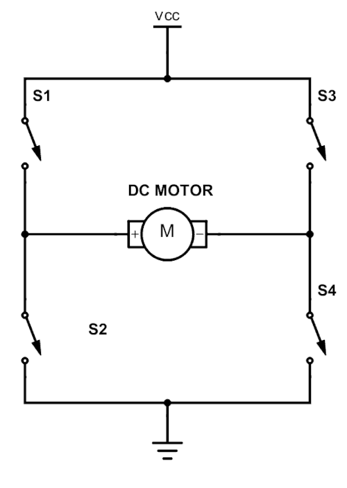
Referring to the image above, if S1 and S4 are closed, current will flow one direction through the motor. However if instead only S3 and S2 are closed current will flow through the motor in the opposite direction. This is how direction is controlled.
The L239D chip serves a second function. In addition to allowing direction control, it also supplies power to the motor in accordance with the pulse width modulated signal coming from the Arduino.
Two wiring diagrams follow. The first is for the motor control circuit. The second is for the stroboscope.
In the circuit above, A1 through A5 on the Arduino are connected to current limiting resistors in series with LEDs. All LEDs are connected to a common ground. A1 through A5 were programmed to light depending on the motor speed setting.
Motor speed was controlled by adjusting the pulse width of the signal from Arduino pin 10. The Arduino did not drive the motor directly. Instead, this signal was sent to the L239D chip pin 1 where it was used to indirectly supply power from an external power supply to the motor.
Pins 8 and 7 on the Arduino are connected to pins 2 and 7 on the L2339D. These control motor direction. If one of these pins is high and the other low, the motor will turn in one direction. However if the reverse is true it will rotate in the opposite direction. If both pins are high or both are low, no power will be supplied to the motor.
The motor is connected to pins 3 and 6.
Pin 8 is connected to the external 9 volt supply, while pin 16 is connected to the Arduino 5 volt line. Pin 16 supplies the 5volt logic to control the the L239D.
Arduino pin 11 is connected to the data pin on the IR Decoder. The other connections on the decoder are to +5 volts and ground.Finally, Arduino pins 5 and 4 are each connected to an LED and current limiting resistor. These indicate motor direction.
Stroboscope
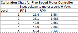
The simple stroboscope circuit follows. It consisted of a signal from a signal generator, not shown, which was used to drive an LED lamp through a 2N222 transistor.
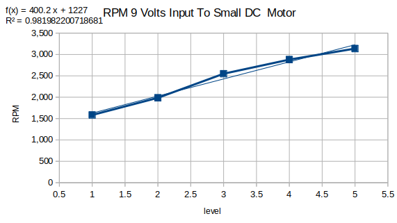
The following data was collected using the stroboscope described above.
Determination Of Codes Sent For Each Button Pressed
In preparation for the motor control sketch it was first necessary to determine the unique Hexadecimal value sent by the IR controller in use. This was accomplished with the short sketch which follows.
Sketch To Determine Code For Each Button Pressed
          /*

          Slightly modified code published by the
           DroneBot Workshop 2017
           http://dronebotworkshop.com
         */

         // Include IR Remote Library by Ken Shirriff
         #include

         // Define sensor pin
         const int RECV_PIN = 11;

         // Define IR Receiver and Results Objects
         IRrecv irrecv(RECV_PIN);
         decode_results results;

         void setup(){
           // Serial Monitor @ 9600 baud
           Serial.begin(9600);
           // Enable the IR Receiver
           irrecv.enableIRIn();
         //  IRrecv.enableIRIn();
         }

         void loop(){
           if (irrecv.decode(&results)){
             // Print Code in HEX
                 Serial.println(results.value, HEX);
                 delay(1000);
                 irrecv.resume();
           }
         }
The Code To Control The Motor
This sketch includes the code to read which button was pressed, and to perform the operation assigned.
Arduino Sketch To Control the Motor
          #include
            int RECV_PIN=11; //RECV_PIN is pin 11
            IRrecv irrecv(RECV_PIN); //instance of IRRecv with arg pin#
            decode_results results; //results is name for decoded value
            int pwm=9; //pin 9 is for pulse width modulation
            int x=0;
            int in1=8;
            int in2=7;
            int ledForward=5;
            int ledReverse=4;
            int led1=A1;
            int led2=A2;
            int led3=A3;
            int led4=A4;
            int led5=A5;

            void setup() {
              // put your setup code here, to run once:
              Serial.begin(9600);
              irrecv.enableIRIn(); //start the receiver
              pinMode(pwm, OUTPUT);
              analogWrite(pwm, x);
              Serial.println("controling dc motors");


              pinMode(in1,OUTPUT);
              pinMode(in2,OUTPUT);

              pinMode(ledForward,OUTPUT);
              pinMode(ledReverse,OUTPUT);

              digitalWrite(ledForward, LOW);
              digitalWrite(ledReverse, LOW);

              pinMode(led1, OUTPUT);
              pinMode(led2, OUTPUT);
              pinMode(led3, OUTPUT);
              pinMode(led4, OUTPUT);
              pinMode(led5, OUTPUT);


              digitalWrite(led1,LOW);
              digitalWrite(led2,LOW);
              digitalWrite(led3,LOW);
              digitalWrite(led4,LOW);
              digitalWrite(led5,LOW);

            }

            void loop() {
              // put your main code here, to run repeatedly:

              if(irrecv.decode(&results )) {
                if(results.value==0xB4B45AA5) {
                  if(x<150) {
                    x=x+30;
                    if(x==30) {
                        digitalWrite(led5, HIGH);
                      }else if
                      (x==60) {
                        digitalWrite(led5,LOW);
                        digitalWrite(led4, HIGH);
                      }else if
                      (x==90){
                        digitalWrite(led5,LOW);
                        digitalWrite(led4,LOW);
                        digitalWrite(led3,HIGH);
                      }else if
                      (x==120){
                        digitalWrite(led5,LOW);
                        digitalWrite(led4,LOW);
                        digitalWrite(led3,LOW);
                        digitalWrite(led2,HIGH);
                      }else if
                      (x==150){
                        digitalWrite(led5,LOW);
                        digitalWrite(led4,LOW);
                        digitalWrite(led3,LOW);
                        digitalWrite(led2,LOW);
                        digitalWrite(led1,HIGH);
                      }

                    analogWrite(pwm,x);
                    Serial.print("faster ");
                    Serial.println(x);

                  if(x>=150){
                    x=150;
                    }

                  }
                  delay(400);
                }

                  if(results.value==0xB4B49A65) {
                    if (x>0) {
                      x=x-30;
                      analogWrite(pwm,x);

                      if(x==120) {
                        digitalWrite(led1,LOW);
                        digitalWrite(led2, HIGH);
                        digitalWrite(led3, LOW);
                        digitalWrite(led4,LOW);
                        digitalWrite(led5,LOW);
                      }else if
                      (x==90){
                        digitalWrite(led1,LOW);
                        digitalWrite(led2,LOW);
                        digitalWrite(led3,HIGH);
                        digitalWrite(led4,LOW);
                        digitalWrite(led5,LOW);
                      } else if
                      (x==60) {
                        digitalWrite(led1,LOW);
                        digitalWrite(led2,LOW);
                        digitalWrite(led3,LOW);
                        digitalWrite(led4,HIGH);
                        digitalWrite(led5,LOW);

                      }else if
                      (x==30){
                        digitalWrite(led1,LOW);
                        digitalWrite(led2,LOW);
                        digitalWrite(led3,LOW);
                        digitalWrite(led4,LOW);
                        digitalWrite(led5,HIGH);
                      }else if
                      (x==0) {
                        digitalWrite(led1,LOW);
                        digitalWrite(led2,LOW);
                        digitalWrite(led3,LOW);
                        digitalWrite(led4,LOW);
                        digitalWrite(led5,LOW);
                      }

                      Serial.print("slower ");
                      Serial.println(x);
                    if(x<0){
                      x=0;

                    }
                      delay(400);

                    }
                  }

                  if(results.value==0xB4B4E21D) {
                    digitalWrite(in1,HIGH);
                    digitalWrite(in2, LOW);
                    digitalWrite(ledForward,HIGH);
                    digitalWrite(ledReverse, LOW);
                      Serial.println("forward ");

                      delay(400);

                    }

                  if(results.value==0xB4B412ED) {
                    digitalWrite(in1,LOW);
                    digitalWrite(in2, HIGH);
                    digitalWrite(ledReverse, HIGH);
                    digitalWrite(ledForward, LOW);
                      Serial.println("backward ");

                      delay(400);

                    }

                  if (results.value==0xB4B49C63){
                    analogWrite(pwm,0);
                    digitalWrite(ledForward, LOW);
                    digitalWrite(ledReverse, LOW);
                    digitalWrite(led1, LOW);
                    digitalWrite(led2, LOW);
                    digitalWrite(led3, LOW);
                    digitalWrite(led4, LOW);
                    digitalWrite(led5, LOW);
                    x=0;

                  }
            //      analogWrite(pwm,x);
                  irrecv.resume();
                }
              }