
- Home Page
- Arduino Main
- Arduino Projects
- Digital yardstick
- The speed of sound
- Barometer and %RH
- IR remote control-LED
- IR remote DC motor
- Relevant Links
- Paul McWhorter
How To Control Devices
Using IR Remote
In this project we will combine the Arduino micro-controller with an IR remote controller to turn on and off a couple of LEDs.
The Project:
IR Remote controllers are everywhere. They are used to control appliances like TV, lights, stereo, and VCR players. Pressing a button on a remote causes a modulated series of infra red pulses to be emitted from the device. A common carrier frequency is 36 khz. Pulses are sent by interrupting the carrier at a much lower rate. A carrier is used instead of simply pulsing an infrared beam to eliminate the possibility of infrared radiation that may be present from interfering with the controlled device. Selectivity is achieved because the receiver in each IR enabled unit is tuned to receive only the carrier frequency. Once the string of pulses is decoded by software in the controlled device, it is used to perform some action.Pulse trains corresponding to pressing various buttons on a remote vary from manufacturer to manufacturer. This is done to prevent unintended responses. You would not want to have the room stereo turn on when you change the channel on your TV.
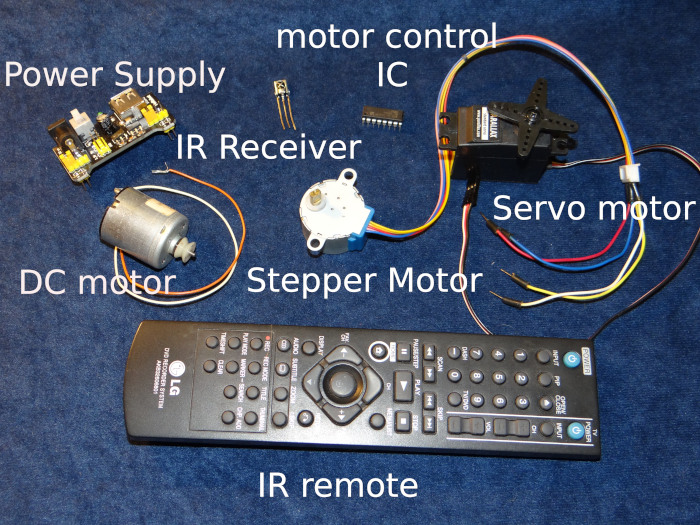
If you are like most people, you probably have a half dozen of these remotes laying around long after whatever they controlled is gone. To put your remote to use, you will need a receiver. These can be salvaged from equipment before disposing of it, or purchased online for a dollar or less. In the experiments that follow, I will use an LG controller and a salvaged IR receiver. in combination with an Arduino, to control an LED, a small DC motor, stepper motor, and a servo motor.
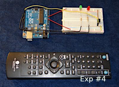
A Short Video Of The IR Controller In Action
In future projects the IR controller will be used to control a small DC motor, a stepper motor, and a servo motor. Some of the same programming contained in this first project will be carried over to the others. For reference here are some of the devices that will be used later.
Wiring
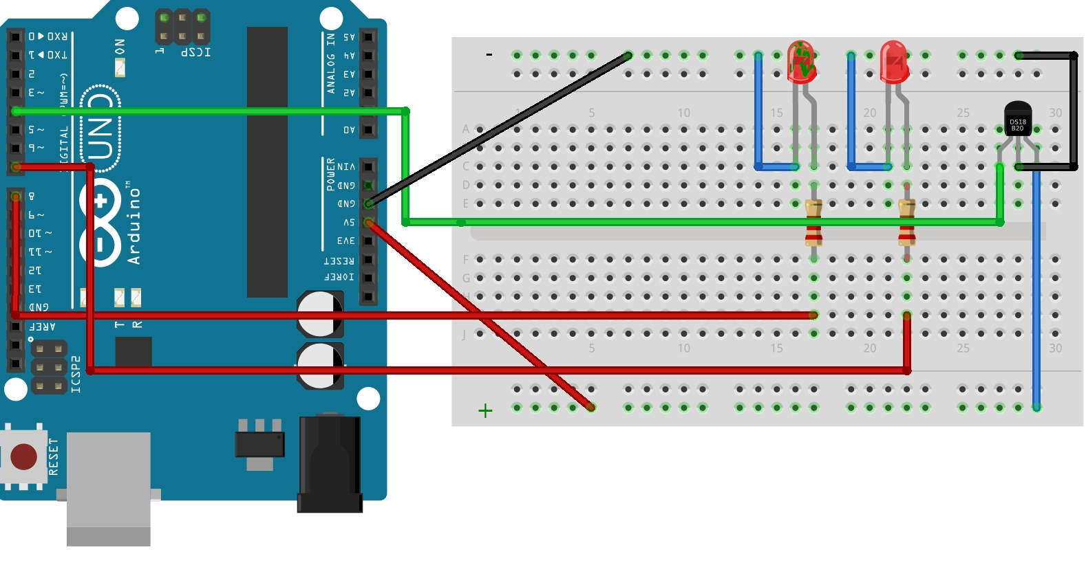
Let's start with the wiring diagram. Connections between the Arduino and the two LEDs and the IR sensor are straight forward. Starting with the sensor, the leftmost pin is the data out pin. The center pin is connected to ground, and the pin on the right is connected to the five volt rail, which in turn is connected to the Arduino five volt supply pin. The two LEDs are connected to pins 7 and 8. When either pin goes high, five volts will be applied to the LED through a 220 ohm current limiting resistor.
Program Operation
In operation, the program senses a specific code sent from the controller, and depending on that code either turns on the red LED for two seconds, or toggles the green LED on or off with each button press. The buttons on the controller used are labeled Display and Return, although any two buttons could have been chosen.
At this point I should point out that the signals received from the controller are translated into Hexadecimal. Hexadecimal is just another numbering system, similar to the decimal system we are all familiar with. Understanding hexadecimal is not important for this application. For the controller used, the hexadecimal number corresponding to pressing the Display button was 0xB4B4A25D. This controls the green LED. The value for pressing the button marked Return was 0xB4B45CA3. This controls the red LED.
At this point I should point out that the signals received from the controller are translated into Hexadecimal. Hexadecimal is just another numbering system, similar to the decimal system we are all familiar with. Understanding hexadecimal is not important for this application. For the controller used, the hexadecimal number corresponding to pressing the Display button was 0xB4B4A25D. This controls the green LED. The value for pressing the button marked Return was 0xB4B45CA3. This controls the red LED.
This is all well and good, but by this time you are probably wondering how you can determine the number transmitted for a given button press. So before we go any further, this should be addressed with a very short and simple Arduino sketch.
Sketch To Determine The Code For Any One Button
Before we address the code the hardware needs to be configured. Follow the wiring diagram shown above for the LED’s. For this purpose, the LED’s are not required. All that is required is that Arduino pin 4 goes to the LED sensor pin 1, sensor pin 2 goes to Arduino ground, and sensor pin 3 goes to Arduino +5 volts.
Sketch To Determine Code For Each Button Pressed
            /* Slightly modified code published by the
            DroneBot Workshop 2017
            http://dronebotworkshop.com
            */

            // Include IR Remote Library by Ken Shirriff
            #include

            // Define sensor pin
            const int RECV_PIN = 4;

            // Define IR Receiver and Results Objects
            IRrecv irrecv(RECV_PIN);
            decode_results results;

            void setup(){
            // Serial Monitor @ 9600 baud
            Serial.begin(9600);
            // Enable the IR Receiver
            irrecv.enableIRIn();
            }

            void loop(){
            if (irrecv.decode(&results)){
            // Print Code in HEX
            Serial.println(results.value, HEX);
            delay(1000);
            irrecv.resume();
            }
            }
The Code To Control The LEDs
Now we will move on to the code to control the LEDs. This code includes the code to read which button was pressed, but adds action to two of them. When the the button labeled Display is pressed the red led will come on for two seconds and then go off. When the button labeled return is pressed it will toggle the green LED on and off with each press. The choice of these two buttons was arbitrary. Any of the other buttons on the controller could have been used, as long as the hex code for those buttons is known to the sketch
Arduino Sketch To Control LEDs
            //include the remote library by Ken Shirriff
            #include

            //define the sensor pin
            const int RECV_PIN = 4;

            //define led pin constants
            const int redPin=7;
            const int yellowPin=8;

            //define integer to remember toggle state
            int togglestate = 0;

            //define IR Receiver and Results Objects
            IRrecv irrecv(RECV_PIN);
            decode_results results;

            void setup() {
            //enable the IR Receiver
            irrecv.enableIRIn();
            pinMode(redPin, OUTPUT);
            pinMode(yellowPin, OUTPUT);
            Serial.begin(9600); //just as a check

            }

            void loop() {

            if (irrecv.decode(&results)){
            switch(results.value){

            case 0xB4B45CA3://red keypad button
            //Turn on LED for 2 seconds
            digitalWrite(redPin, HIGH);
            delay(2000);
            digitalWrite(redPin, LOW);
            Serial.println(results.value,HEX);
            break;

            case 0xB4B4A25D://yellow heypad button
            //Toggle LED on or off
            if(togglestate==0){
            digitalWrite(yellowPin, HIGH);
            togglestate=1;
            }
            else{
            digitalWrite(yellowPin, LOW);
            togglestate=0;
            }
            Serial.println(results.value, HEX);
            break;

            }
            irrecv.resume();
            }
            }